Records of Nintendo Switch Hardware Repair
Records of Hardware Repairs: Emerging from the Software Realm and Taking a Step Towards Hardware Excellence
The Utility
You can gain insights into the hardware aspects of the Nintendo Switch. If interested, you can also engage in hands-on maintenance of your own gaming console, learning about precautions to take during regular usage to prevent/avoid human-induced damages, thereby prolonging the lifespan of these hardware components.

Relevant Content
Pertinent Content
Approach
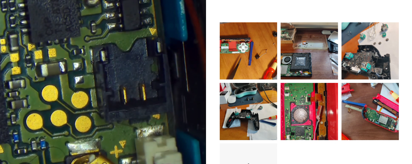
Case Study - Right Joy-Con Not Charging, LED Off
Observation
The right Joy-Con fails to charge, with its LED inactive. Drawing insights from remote conversations (an almost mystical art, challenging to articulate verbally, perhaps a side effect of prolonged software tinkering, fostering an understanding of the mystical and remote), it’s deduced that the issue likely resides within the right Joy-Con controller, not the console’s rails (if multiple right Joy-Con controllers are available, direct substitution for testing can yield more precise diagnostics, pinpointing the issue to the right controller).
Diagnosis
Upon acquiring the malfunctioning controller, observations confirm: pressing buttons yields no response, inserting it into the console prompts an audible system acknowledgment, but the battery indicator shows severe depletion (in red). While the console indicates normal charging for the right controller, the faulty controller remains in a depleted state, incapable of charging.
Disassembling the right Joy-Con, systematic component replacements ensue: battery swap (followed by comprehensive system testing, with the fault persisting), rail replacement (again, with no resolution), disassembling the motherboard, disconnecting all extraneous peripheral cables to isolate other non-essential hardware components (a myriad of them, including joystick cables, ZR cables, rail lights, button cables, rail power and signal cables, motor cables, motor power, and mibo cables, Bluetooth cables), then reassembling with only the motherboard and a functional rail connected to the Switch console for testing, yet the fault remains. A revelation!
Both the rail and its cables are verified new and functional, implicating the motherboard as the likely culprit.
Embarking on chip-level repairs, a realm beyond my realm of expertise and manual dexterity (revealing the precarious nature of hardware endeavors), a flurry of Google tutorials ensue, eventually finding inspiration from videos by “Yang Geng Papa” and “Tong Xin Zai Zai” (coupled with some consultations with my hardware guru, inevitably leading to purchasing a pack of cigarettes for him later). After extensive multimeter measurements, the issue (or at least one of them) is pinpointed to a fuse adjacent to the power socket.
A brief educational aside (knowledge typically acquired in middle or high school physics; a momentary critique of the educational landscape: inundated with knowledge seemingly sufficient for each student to embark on atomic bomb development, yet few are adept at the simple task of repairing household electronic components through basic component replacement and soldering; however, reflecting on obtaining a driver’s license does not guarantee immediate driving proficiency; such is the journey of life, perpetually filled with learning and overcoming challenges): setting the multimeter to the resistance buzz mode (indicating continuity, whereby touching both probes triggers a buzz, signifying a clear path between the probes), no buzz is heard when placed across the fuse in question (its position detailed in the “Inspiration Source” video), whereas the same test on a functional controller elicits a buzz. Eureka!
Resolution
Various repair methods are available, ideally involving fuse replacement on the motherboard (though this entails lengthy procurement and delivery times and significant investment in equipment). Following “Yang Geng Papa’s” example, bridging the fuse with a soldering iron yields success. Reconnecting to the console, gradually reattaching cables, and retesting restores functionality. Fault resolved.
Another potential issue in series: a faulty charging IC on the motherboard, necessitating microscope and hot air gun intervention…
Case Study - Pro Controller and Joy-Con Joystick Drift
Observation
The left Joy-Con exhibits joystick drift, manifesting as involuntary character movement during gameplay (an unintended foray into autonomous intelligence), or uncontrollable braking and directional instability…
Diagnosis
Connected to the console, a simple joystick calibration reveals a failure to reset to center, causing the cursor to wander aimlessly.
Resolution
Procuring fourth-generation Joy-Con joysticks and replacing them resolves the issue.
Procuring Pro Controller joysticks, soldering, and replacing the entire joystick assembly; or replacing the worn-out sliding pieces on the joystick’s side with new ones.
Case Study - Joy-Con LED Inactivity
Observation
The SL and SR buttons on the left Joy-Con fail to respond, with their LEDs remaining inactive; they cannot be paired with a new console (yet function normally when connected to an existing console).
Diagnosis/Resolution
Procuring replacement cables for this side prompts an intuitive need for cable replacement. The process is straightforward, as detailed in accessible instructional videos.
…
Case Study - R Key Repair

Observation
The design of the R key (directly soldered onto the right Joy-Con motherboard) and its automated soldering process have long plagued Nintendo with criticism (though it remains a masterpiece balancing price and functionality), with the R key showing no response upon pressing.
The fault divides into two categories: solder pad detachment and intact solder pads, with solder pad detachment being the more common occurrence (owing to the minuscule size of the solder pads).
Diagnosis/Resolution
For intact solder pads, applying some flux and replacing the faulty microswitch resolves the issue.
For detached solder pads, typically, connecting the two pins on the microswitch (the middle pin and any one of the side pins) to specific locations on the motherboard via jumper wires (as evident in the video below, eliminating the need for extensive technical expertise). Caveats and pitfalls include:
- Power off and disassemble the Joy-Con motherboard.
- Yes, it’s cumbersome but necessary, facilitating ease of operation (given the Joy-Con’s small size) and preventing accidental contact of the soldering iron with the Joy-Con’s plastic casing and other components.
- Subsequent testing only requires connecting the rail and battery to directly test the R key repair.
- [Optional] Solder a bit of solder onto the middle pin of the microswitch (very fine solder, avoiding short circuits with other pins).
- Start by soldering the sides of the microswitch first for stability.
- Apply flux before soldering, clean the area around the microswitch on the motherboard, hold the new microswitch in place, and solder.
- Note: Avoid allowing solder to touch (connect) the metal dot on the left side of the microswitch, as novices may inadvertently fall into this pitfall (the other side aims for more solder, ensuring a firmer hold), as testing would then reveal all keys malfunctioning.
- 拿着飞线,先焊中间那个针脚,然后是它所连接的‘第’字左侧的金属小圆片
- 注意:不要让飞线(一般是非绝缘的)连接到微动中间针脚和这个‘第’字左侧的金属小圆片中途路过的金属小圆点。否则测试会发现所有的按键都失灵。
- 拿着第二根飞线,根据现实情况,焊任意一侧针脚到‘第’字下方的金属小圆点
- 注意:同样不让让飞线的中途位置碰触到其他的金属小圆点。
- 焊好确认固定了,用万用表的接通性测试(两点间接通的情况下会发出‘哔’音);再连接滑轨和电池,测试R键的修复情况
- 假设各个按键都非常完美的情况下,给新的飞线位置焊点都涂上AB胶
- 这样确保焊电和主板的固定能持久化
- 我遇到一种情况因为不打胶固定,单独主板和滑轨电池的测试也ok;而最后全部组装拼好以后就又不能识别R键了,又得按上面的步骤重新来过。超级耗时、考验耐心和注意力。
本章节参考
1 | switch JC手柄 R键维修 |
友情提示:youtube如果打不开,请先打开网络加速器,然后粘贴详细网址后回车访问
Hardware Exploits: Unleashing the Full Potential
Hardware exploits primarily target the following models in descending order of price: OLED version (the latest at the moment), Lite version, extended battery version, and standard version.
Summary of Hardware Exploits (from old to new)
- sxcore exploit chip (dated, around 2021 or earlier)
- Domestic exploit chips
- Without buttons
- Label on ribbon cable: (MV1.7.2) Purple LED blinking at startup, then turns green
- Raspberry Pi-based exploit chips (featuring golden reset buttons and more)
- TFP chip (also known as Raspberry Pi)
- Waveshare RP2040 development board
- Hwfly Core RP2040
- Picofly Core RP2040
- Label on ribbon cable: (New 2040plus) Blue LED blinking at startup, then turns green
Sources of Inspiration
羊羹爸爸 尝试维修5块Switch Joy Con故障主板,能修好几块呐?
[Switch手柄无反应,灯不亮,不能充电,连接不上](